555 Timer contest entry
Turnin' it up to 11 555
When the 555 Timer contest was announced, it seemed almost inevitable that I'd think up something crazy to enter. After considering and quickly discounting a 555 based nixie clock and various dangerous high-voltage ideas, the 'Complex/Extreme' category particularly caught my eye.
What could be done with a lot of 555's ? Well a 555 can flash a LED, so lots of 555's could flash lots of LEDs, and you can never have too any flashing LEDs. But how many? And in what shape? The answer became pretty obvious, especially on the realisation that the number five hundred and fifty-five divides by three, and has three digits...
A LED display with five hundred and fifty-five 555's, flashing 555 LEDs displaying a big "555"!

It just has to be the absolute 555est way of using 555 555's. There's something about this that's so 555, it's like, how much more 555 could this be?, and the answer is none.
 So how best to arrange 185 (555/3) LED flasher circuits in the
shape of a "5" digit...?
So how best to arrange 185 (555/3) LED flasher circuits in the
shape of a "5" digit...?
I hacked up a quick program to count the number of white pixels in a bitmap file, and played around with different fonts & sizes, plus some manual pixel-level tweaking to get a "5" with exactly 185 pixels.
 The circuitry to flash a LED seemed obvious, but I wanted
to play around to get it as simple as possible to minimise the part count, and make it
routable on a single layer PCB.
The circuitry to flash a LED seemed obvious, but I wanted
to play around to get it as simple as possible to minimise the part count, and make it
routable on a single layer PCB.
Another reason was that I wanted some control over flash rate to optimise the visual effect more easily than resoldering 500+ components, and the easiest way seemed to be by varying the supply voltage. A normally useful feature of the standard 555 oscillator circuit is that it has very good stability with supply voltage variations as the charge rate and trigger thresholds are both proportional to supply voltage, however this is exactly what I didn't want in this case.
I came up with this circuit, which addresses both issues. Firstly, putting
the LED in series with the discharge pin saves a resistor and makes it easier for
single-layer PCB layout. (I've shown the internal discharge transistor in the 555 to make
it clearer how this works.)
Secondly, by having the LED in the capacitor's charge path, the frequency now becomes
proportional to the ratio of the supply voltage to the LED's (relatively fixed) forward
voltage, so flash rate varies significantly with supply voltage, allowing easy global
flash-rate control.

 This circuit could be laid out fairly neatly as a modular 'tile' on a single
PCB layer, which could then be cut & pasted into the required shape according to the
bitmap grid for the "5" shape matrix.
This circuit could be laid out fairly neatly as a modular 'tile' on a single
PCB layer, which could then be cut & pasted into the required shape according to the
bitmap grid for the "5" shape matrix.
To keep things small but manageable, I decided to use 0603 passives and LED - Texas do make a 555 in a TSSOP package, and I could have used 0402 parts, but this would have been pushing the capabilities of homebrewed PCBs and my pick & place machine.
The tile ended up being 0.4" square, giving a PCB size around 11.1x6.8" for a single digit, so three identical PCBs would make the full display, and be about 2 feet wide.
I deliberately decided not to include supply decoupling capacitors at this stage, as cross coupling due to supply noise can sometimes produce some interesting chaotic effects, and caps could easily be added later if necessary across the horizontal power tracks between each row. A cap for each timer would probably have been overkill.
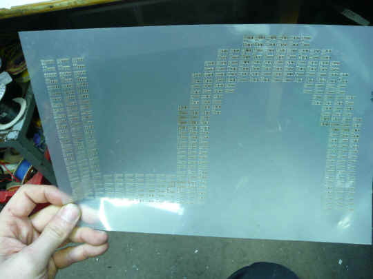
 The complete PCB layout - the power rails run
horizontally, and were originally connected together by copper pours on each side, but
instead of solid pours filling the board, I decided it would look nicer if the power
tracks outlined the shape of the digit - small gaps at two corners separate the rails.
The complete PCB layout - the power rails run
horizontally, and were originally connected together by copper pours on each side, but
instead of solid pours filling the board, I decided it would look nicer if the power
tracks outlined the shape of the digit - small gaps at two corners separate the rails.
Click image for a 400DPI GIF, or Here for actual-size PDF version
Gerbers or P-Cad2006 PCB file are available on request!.
 OK, so everything was set to go... However I then hit a major
problem - I couldn't get my cheap Chinese lasercutter to
make an accurate enough solder-paste stencil.
OK, so everything was set to go... However I then hit a major
problem - I couldn't get my cheap Chinese lasercutter to
make an accurate enough solder-paste stencil.
After several attempts (each taking over an hour), it just kept introducing odd
non-linear distortions, which made it impossible to line up correctly. It works reasonably
well over smaller areas, but for a stencil of this size with 0603's, it just wasn't going
to be good enough, and hand-pasting 8880 blobs of paste was never going to be an option.
Although I was prepared to buy the 555s and use a load of photoresist PCB laminate to make
this, I really didn't think the additional cost of a stainless stencil was justifiable, so
I pretty much abandoned the project.
However a couple of days before the closing date, I was idly browsing the contest rules, and noticed that
it didn't explicitly say that you had to build your design, just
"prove it works somehow". As this was a modular design, I
figured that a smaller section would be enough to prove the concept, and although I'd
normally hand-assemble a small board like this, assembling on my pick & place machine
would show that the full version could have been built in a realistic timescale.
It was a weekend, so there was no way I could get hold of any quantity of SO-8 555's
before the deadline, but found I already had a tube of ten in my component stock, so this
alone determined the size of the board I would build, a 3x3 section.
Video of assembly. The pick & place footage is a bit fragmented as the extra light needed for the camera often freaked out the vision system on the machine & it kept rejecting parts. BTW the annoying wailing noise is the pick-up vacuum pump.
 Assembled PCB (after decoupling caps added - see later).
Video of tests. Lack of decoupling shows very obvious cross-coupling between most of
the timers, to the extent that they nealy all stay in sync with each other - you;d
normally expect them to drift apart quickly due to slight differences in componant values
The reason for this is that when the first (fastest) timer triggers, it introduces
a small voltage spike on the supply, and this spike can be enough to cause any other
timers that were close to their trigger threshold to trigger immediately.
Adding some 100n caps across the power rails makes an obvious difference to this
behaviour, although there is still some synchronisation occurring.
 ..and this is how big the full version would have been....
Estimated current draw is 2-4 amps, depending on supply voltage